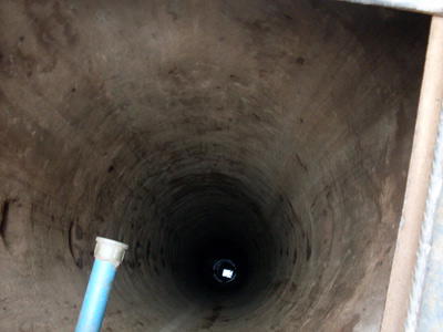
The substance, suspected petroleum product
CONTINUED FROM LAST EDITION
Conductor casing Conductor casing is the first string set below the structural casing (i.e., drive pipe or marine conductor run to protect loose near-surface formations and to enable circulation of drilling fluid).

The substance, suspected petroleum product
The conductor isolates unconsolidated formations and water sands and protects against shallow gas.
This is usually the string onto which the casing head is installed. A diverter or a blowout prevention (BOP) stack may be installed onto this string.
When cemented, this string is typically cemented to the surface or to the mudline in offshore wells.
Surface casing
Surface casing is set to provide blowout protection, isolate water sands, and prevent lost circulation. It also often provides adequate shoe strength to drill into high-pressure transition zones.
In deviated wells, the surface casing may cover the build section to prevent keyseating of the formation during deeper drilling. This string is typically cemented to the surface or to the mudline in offshore wells.
Intermediate casing
Intermediate casing is set to isolate:
—Unstable hole sections
—Lost-circulation zones
—Low-pressure zones
—Production zones
It is often set in the transition zone from normal to abnormal pressure. The casing cement top must isolate any hydrocarbon zones. Some wells require multiple intermediate strings. Some intermediate strings may also be production strings if a liner is run beneath them.
Production casing
Production casing is used to isolate production zones and contain formation pressures in the event of a tubing leak. It may also be exposed to:
—Injection pressures from fracture jobs
—Downcasing, gas lift
—The injection of inhibitor oil
A good primary cement job is very critical for this string.
Liner
Liner is a casing string that does not extend back to the wellhead, but is hung from another casing string. Liners are used instead of full casing strings to:
—Reduce cost
—Improve hydraulic performance when drilling deeper
—Allow the use of larger tubing above the liner top
—Not represent a tension limitation for a rig
Liners can be either an intermediate or a production string. Liners are typically cemented over their entire length.
—Tieback string
Tieback string is a casing string that provides additional pressure integrity from the liner top to the wellhead. An intermediate tieback is used to isolate a casing string that cannot withstand possible pressure loads if drilling is continued (usually because of excessive wear or higher than anticipated pressures).
Similarly, a production tieback isolates an intermediate string from production loads. Tiebacks can be uncemented or partially cemented.
Tubing
Tubing is the conduit through which oil and gas are brought from the producing formations to the field surface facilities for processing.
Tubing must be adequately strong to resist loads and deformations associated with production and workovers. Further, tubing must be sized to support the expected rates of production of oil and gas. Clearly, tubing that is too small restricts production and subsequent economic performance of the well.
Tubing that is too large, however, may have an economic impact beyond the cost of the tubing string itself, because the tubing size will influence the overall casing design of the well.
Properties of casing and tubing
The American Petroleum Inst. (API) has formed standards for oil/gas casing that are accepted in most countries by oil and service companies. Casing is classified according to five properties:
—The manner of manufacture
—Steel grade
—Type of joints
—Length range
—The wall thickness (unit weight)
Almost without exception, casing is manufactured of mild (0.3 carbon) steel, normalized with small amounts of manganese. Strength can also be increased with quenching and tempering. API has adopted a casing “grade” designation to define the strength of casing steels. This designation consists of a grade letter followed by a number, which designates the minimum yield strength of the steel in ksi (103 psi).
Pipe strength
To design a reliable casing string, it is necessary to know the strength of pipe under different load conditions. The most important mechanical properties of casing and tubing are:
—Burst strength
—Collapse resistance
—Tensile strength
—API connection ratings
While a number of joint connections are available, the API recognizes three basic types:
—Coupling with rounded thread (long or short)
—Coupling with asymmetrical trapezoidal thread buttress
—Extreme-line casing with trapezoidal thread without coupling
Threads are used as mechanical means to hold the neighbouring joints together during axial tension or compression. For all casing sizes, the threads are not intended to be leak resistant when made up. API Spec. 5C2, Performance Properties of Casing, Tubing, and Drillpipe, provides information on casing and tubing threads dimensions.
In round threads, two small leak paths exist at the crest and root of each thread. Buttress threads have a much larger leak path along the stabbing flank and at the root of the coupling thread. API connections rely on thread compound to fill these gaps and provide leak resistance. The leak resistance provided by the thread compound is typically less than the API internal leak resistance value, particularly for buttress connections. The leak resistance can be improved by using API connections with smaller thread tolerances (and, hence, smaller gaps), but it typically will not exceed 5,000 psi with any long-term reliability. Applying tin or zinc plating to the coupling also results in smaller gaps and improves leak resistance.
Round-thread casing-joint strength
Proprietary connections
Special connections are used to achieve gas-tight sealing reliability and 100% connection efficiency (joint efficiency is defined as a ratio of joint tensile strength to pipe body tensile strength) under more severe well conditions. Severe conditions include:
—High pressure (typically 5,000 psi)
—High temperature (typically 250°F)
—A sour environment
—Gas production
—High-pressure gas lift
—A steam well
—A large dogleg (horizontal well)
Also, efficiency in flush joint, integral joint or other special clearance applications improves connections. A large diameter (16 in.) pipe improves the stab-in and makeup characteristics; galling should be reduced (particularly in CRA applications and tubing strings that will be re-used); and connection failure under high torsional loads (e.g., while rotating pipe) should be prevented.
The improved performance of many proprietary connections results from one or more of these features not found in API connections:
—More complex thread forms
—Resilient seals
—Torque shoulders
—Metal-to-metal seals
The “premium” performance of most proprietary connections comes at a “premium” cost. Increased performance should always be weighed against the increased cost for a particular application. As a general rule, it is recommended to use proprietary connections only when the application requires them. “Premium” performance may also be achieved using API connections if certain conditions are met.
Those conditions are:
—Tighter dimensional tolerance
—Plating applied to coupling
—Use of appropriate thread compound
—Performance verified with qualification testing
The performance of a proprietary connection can be reliably verified by performing three steps:
Audit the manufacturer’s performance test data (sealability and tensile load capacity under combined loading)
Audit the manufacturer’s field history data
Require additional performance testing for the most critical applications
When requesting tensile performance data, make sure that the manufacturer indicates whether quoted tensile capacities are based on the ultimate tensile strength (i.e., the load at which the connection will fracture, commonly called the “parting load”) or the yield strength (commonly called the “joint elastic limit”). If possible, it is recommended to use the joint elastic limit values in the design so that consistent design factors for both pipe-body and connection analysis are maintained. If only parting load capacities are available, a higher design factor should be used for connection axial design.
Connection failures
Most casing failures occur at connections. These failures can be attributed to:
—Improper design or exposure to loads exceeding the rated capacity
—Failure to comply with makeup requirements
—Failure to meet manufacturing tolerances
—Damage during storage and handling
—Damage during production operations (corrosion, wear, etc.)
Connection failure can be classified broadly as:
—Leakage
—Structural failure
—Galling during makeup
—Yielding because of internal pressure
—Jump-out under tensile load
—Fracture under tensile load
—Failure because of excessive torque during makeup or subsequent operations
Avoiding connection failure is not only dependent upon selection of the correct connection, but is strongly influenced by other factors, which include:
—Manufacturing tolerances
—Storage (storage thread compound and thread protector)
—Transportation (thread protector and handling procedures)
—Running procedures (selection of thread compound, application of thread compound, and adherence to correct makeup specifications and procedures)
The overall mechanical integrity of a correctly designed casing string is dependent upon a quality assurance program that ensures damaged connections are not used and that operations personnel adhere to the appropriate running procedures.
Connection design limits
The design limits of a connection are not only dependent upon its geometry and material properties, but are influenced by:
—Surface treatment
—Phosphating
—Metal plating (copper, tin, or zinc)
—Bead blasting
—Thread compound
—Makeup torque
—Use of a resilient seal ring (many companies do not recommend this practice)
—Fluid to which connection is exposed (mud, clear brine, or gas)
—Temperature and pressure cycling
—Large doglegs (e.g., medium- or short-radius horizontal wells)
Risk factors
Threads on ends are particularly liable to damage by rough handling, even though thread protectors are fitted. Threaded ends so damaged may be cut and re-threaded in the oil-fields, where special machinery is usually available. Bends and dents, if not too severe, may also be straightened by special machinery in the larger oilfield centres, but, as oilwell casing is subject to high pressure, such repairs must be tested and inspected by technical processes, which are expensive.
Disclaimer
Comments expressed here do not reflect the opinions of Vanguard newspapers or any employee thereof.